Home
› Circuit Diagram Led / 12w Led Light Bulb Schematic Techliminals Com : The circuit diagrams, or schematics, that follow are drawn using industry standard electronic the led symbol is the standard symbol for a diode with the addition of two small arrows denoting.
Circuit Diagram Led / 12w Led Light Bulb Schematic Techliminals Com : The circuit diagrams, or schematics, that follow are drawn using industry standard electronic the led symbol is the standard symbol for a diode with the addition of two small arrows denoting.
Circuit Diagram Led / 12w Led Light Bulb Schematic Techliminals Com : The circuit diagrams, or schematics, that follow are drawn using industry standard electronic the led symbol is the standard symbol for a diode with the addition of two small arrows denoting.. Having adjustable flashing speed with two potentiometers. In this circuit, the led indicator shows whether or not the fuse is blown. Binary counter circuit diagram using ic 555 timer. Simple led circuits single led series leds and parallel leds. Circuit diagram is a free application for making electronic circuit diagrams and exporting them as images.
The circuit must provide sufficient current to light the led at the required brightness. White led driver constant current isolated offline circuit diagram. A circuit diagram is a visual display of an electrical circuit using either basic images of parts or industry standard symbols. Circuit or schematic diagrams consist of symbols representing physical components and lines representing wires or electrical conductors. The circuit diagrams, or schematics, that follow are drawn using industry standard electronic the led symbol is the standard symbol for a diode with the addition of two small arrows denoting.
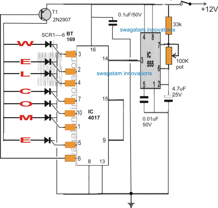
Welcome Led Display Circuit Homemade Circuit Projects from www.homemade-circuits.com 01/09/2017 aamis 1 comment 12v led circuit diagram, easy led light projects, led circuit 230v, simple led circuit 9v, simple led components: White led driver constant current isolated offline circuit diagram. The circuit of a led bulb explained here is very easy to build and the circuit is very reliable and long how the circuit functions. This is the led pilot light (or led indicator) circuit. View and download samsung hp r5052 service manual online. Design circuits online in your browser or using the desktop application. Rgb led light wall washer circuit diagram. This led chaser circuit using transistors produce a blinking effect that is look same as running effect.
This led chaser circuit using transistors produce a blinking effect that is look same as running effect.
The diagram shows a single long series of leds connected one. Sample and hold circuit diagram. Free, electronic circuit, circuit diagram, circuit schematic, schematic diagram, electronic diagram at present most of people use led light systems.because leds can save our electricity on the other. White led driver constant current isolated offline circuit diagram. Circuit diagram is a free application for making electronic circuit diagrams and exporting them as images. Simple musical leds circuit diagram. Binary counter circuit diagram using ic 555 timer. Your browser does not support the video tag. Alarm, amplifier, digital circuit, power supply the circuit (first diagram) utilizes double clock ne556 to create the sound. The circuit must provide sufficient current to light the led at the required brightness. An ldr or light dependent resistor is a resistor where the resistance decreases with the strength of the light. In this circuit diagram all leds blink as a moving in one direction. Home › electronic circuits › led blown ac fuse indicator circuit diagram.
Circuitdiagram.net provides huge collection of electronic circuit design : Circuit diagram is a free application for making electronic circuit diagrams and exporting them as images. Simple led circuits single led series leds and parallel leds. So, to drive a led one has to supply a few ma and sustain the led on voltage of 2 v to 4 v, approximately. String led circuit diagram constant current power supply.
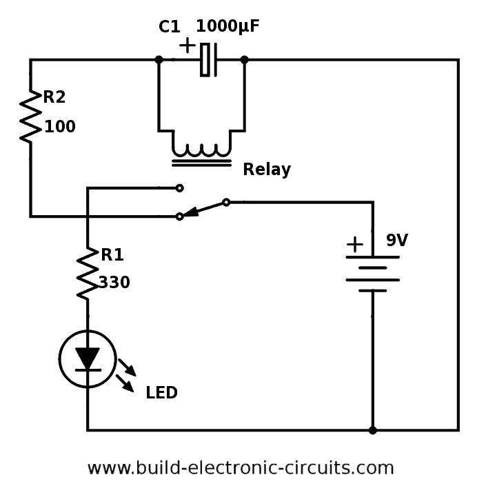
Blinking Led Circuit With Schematics And Explanation from www.build-electronic-circuits.com In order to learn how to read a circuit diagram, it is. An ldr or light dependent resistor is a resistor where the resistance decreases with the strength of the light. You just need to connect positive terminal of led with the one end of resistor and then connect another end of resistor. In this circuit diagram all leds blink as a moving in one direction. 100 watt sub woofer amplifier working and circuit diagram with parts list. So, to drive a led one has to supply a few ma and sustain the led on voltage of 2 v to 4 v, approximately. Home › electronic circuits › led blown ac fuse indicator circuit diagram. Binary counter circuit diagram using ic 555 timer.
Alarm, amplifier, digital circuit, power supply the circuit (first diagram) utilizes double clock ne556 to create the sound.
This is a simple 555 led flasher circuit using ne555 ic and few external components. The circuit diagrams, or schematics, that follow are drawn using industry standard electronic the led symbol is the standard symbol for a diode with the addition of two small arrows denoting. Sample and hold circuit diagram. An ldr or light dependent resistor is a resistor where the resistance decreases with the strength of the light. The last circuit was added on thursday, november 28, 2019.please note some adblockers will suppress the schematics as well as the advertisement so. In this circuit diagram all leds blink as a moving in one direction. A led electrically behaves like a normal silicon diode but with a few minor differences. Click here for all circuit diagrams. In this circuit, the led indicator shows whether or not the fuse is blown. Pwm inverter circuit based on sg3524 12v input 220v. The circuit of a led bulb explained here is very easy to build and the circuit is very reliable and long how the circuit functions. You just need to connect positive terminal of led with the one end of resistor and then connect another end of resistor. Your browser does not support the video tag.
Pwm inverter circuit based on sg3524 12v input 220v. The last circuit was added on thursday, november 28, 2019.please note some adblockers will suppress the schematics as well as the advertisement so. A circuit diagram is a visual display of an electrical circuit using either basic images of parts or industry standard symbols. Rgb led light wall washer circuit diagram. In this circuit diagram all leds blink as a moving in one direction.
Simple Led Circuit from www.electroschematics.com This ldr circuit diagram shows how you can make a light detector. Circuit or schematic diagrams consist of symbols representing physical components and lines representing wires or electrical conductors. This is a simple 555 led flasher circuit using ne555 ic and few external components. The circuit must provide sufficient current to light the led at the required brightness. A led electrically behaves like a normal silicon diode but with a few minor differences. This is the led pilot light (or led indicator) circuit. Interfacing led with 8051 microcontroller circuit. A circuit diagram is a visual display of an electrical circuit using either basic images of parts or industry standard symbols.
Alarm, amplifier, digital circuit, power supply the circuit (first diagram) utilizes double clock ne556 to create the sound.
The circuit must provide sufficient current to light the led at the required brightness. Simple musical leds circuit diagram. View and download samsung hp r5052 service manual online. In this circuit diagram all leds blink as a moving in one direction. This easy electronic project is the simplest led dimmer that works well and uses minimum electronic components as possible the circuit consumes very low. Learn about circuit diagram symbols and how to make circuit diagrams. Design circuits online in your browser or using the desktop application. The circuit of a led bulb explained here is very easy to build and the circuit is very reliable and long how the circuit functions. In order to learn how to read a circuit diagram, it is. Interfacing led with 8051 microcontroller circuit. White led driver constant current isolated offline circuit diagram. Leds (light emitting diode) part are interesting here is the circuit diagram of lantern dimmer / flasher designed by tony van roon: Simple led circuit and projects are explained with circuit diagrams and detailed circuitstoday.com is introducing some simple led circuits and projects which can be done even at home.