Rj 45 Connector Diagram - Rj45 Socket Wiring Diagram Uk - Wiring Diagram - Rj45 cross over ethernet cable pinout how to crimp an rj45 ethernet cable.
Rj 45 Connector Diagram - Rj45 Socket Wiring Diagram Uk - Wiring Diagram - Rj45 cross over ethernet cable pinout how to crimp an rj45 ethernet cable.. You can send up to 4 telephone lines on one 4 pair cable that terminates at a rj45 (8p8c) jack. Ethernet cable utp rj45 wiring diagram there are two standards that are used for rj45 connector wiring. Well discuss some options for connecting phones with rj11 connectors to an rj45 port. Orange & white pin 2: Rj45 pinout for t568a standard
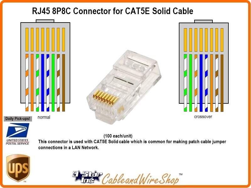
The rj45 connector has 8 pins as shown above. Rj stands for registered jack, and the true rj45 connector was originally developed as part of the standardized telecommunication network interface for the purpose of connecting telephone networks. If not, the arrangement will not function as it ought to be. Ethernet cables rj45colors crossover this diagram shows how ethernet cable color coding works. Figure 1 is the wiring scheme for the plug side of an rj connector.
Ethernet cable utp rj45 wiring diagram there are two standards that are used for rj45 connector wiring.
The diagram is shown with the hook clip on the underside. Usb to cat5 wiring diagram new 1m usb to down angle micro usb cable. Rj45 cross over ethernet cable pinout how to crimp an rj45 ethernet cable. So if you are looking for a connector to communicate through rj45 protocol then this connector might be the right choice for you. The ethernet cable,connectors and connector crimper are available at local computer store or most electrical centers. Registered jack 45 (rj45) is a standard type of physical connector for network cables. The rj45(s) jack is rarely used in telephone applications but a standard version of the 8p8c modular connector used by rj45(s) is used in ethernet networks and the connector is often referred to as rj45 in this context. This video lecture explains the pins and wiring in ethernet cables and rj45 plugs. There are multiple pinouts for rj45 connectors including straight through (t568a or t568b), crossover, rolled, t1, and loopback. Ethernet cable utp rj45 wiring diagram there are two standards that are used for rj45 connector wiring. This article illustrates the serial pinouts of opengear rj45 serial ports, past and present. Pin 1, 2, 3, 6 are for data transfer while pin 4, 5, 7, 8 are for poe power supply. Molex rj45 connector, rj45 magjack breakout, transceiver board.
This video lecture explains the pins and wiring in ethernet cables and rj45 plugs. They are eia/tia 568a and eia/tia 568b. 2 db9 female to rj45 female modular adapters this is pretty much just like the crossover cable but with a different pinout: The diagram is shown with the hook clip on the underside. The copper splicing tabs on the plug will pierce into each of the eight conductors.

568 a and 568 b.svg 990 × 765;
The locking tab will cinch onto the outer jacket of the cable. Ponent absolute question and answer thread v 3 ask your. Figure 1 is the wiring scheme for the plug side of an rj connector. This high quality insert is for use in all keystone wall plates. Cat5, cat5e, cat6 cable is frequently used for wiring telephone jacks. The ethernet cable,connectors and connector crimper are available at local computer store or most electrical centers. If not, the arrangement will not function as it ought to be. Rj45 colors wiring guide diagram tiaeia 568 ab. This video lecture explains the pins and wiring in ethernet cables and rj45 plugs. Clarification of the various colour code standards for wiring rj45 connectors. This article explain how to wire cat 5 cat 6 ethernet pinout rj45 wiring diagram with cat 6 color code , networks have become one of the essence in computer world and for better internet facilities ti gets extremely important to built a good, secured and reliable network. A pinout is a specific arrangement of wires that dictate how the connector is terminated. Whats special about these modules 50u gold plated contacts.
There are multiple pinouts for rj45 connectors including straight through (t568a or t568b), crossover, rolled, t1, and loopback. Diagrams representing the arrangement of contacts in jack sockets. Trim off any nylon strands or wire guides. A rj45 connector is a modular 8 position, 8 pin connector used for terminating cat5e or cat6 twisted pair cable. Rj45 pinout diagram shows the way how that connector provides communication with network devices.

This video lecture explains the pins and wiring in ethernet cables and rj45 plugs.
• another way of remembering the colour coding is to simply switch the green set of wires in place Diagrams representing the arrangement of contacts in jack sockets. For the db9 female connector pin 1 is the top right and pin 6 is the bottom right it's certainly possible to wire your rj45/db9 connectors following this pinout. Rj stands for registered jack, and the true rj45 connector was originally developed as part of the standardized telecommunication network interface for the purpose of connecting telephone networks. We look at the 568a and 568b color codes, what they mean, and why they're important. Rj45 connectors are commonly seen with ethernet cables and networks. You can send up to 4 telephone lines on one 4 pair cable that terminates at a rj45 (8p8c) jack. You may follow the wire order below to arrange the wires of your rj45 connector. Ethernet cable utp rj45 wiring diagram there are two standards that are used for rj45 connector wiring. Cat cables, usart modules, rs232 to ttl converters, rj45 modules. This chart should be used as a guide for telephone socket adapter type data. This video lecture explains the pins and wiring in ethernet cables and rj45 plugs. Green & white pin 4: