Home
› Types Of Electrical Circuits Diagrams : Schematic Symbols Electronics Circuit Electrical Circuit Diagram Electrical Symbols - We know that electric current flows in a closed circuit.
Types Of Electrical Circuits Diagrams : Schematic Symbols Electronics Circuit Electrical Circuit Diagram Electrical Symbols - We know that electric current flows in a closed circuit.
Types Of Electrical Circuits Diagrams : Schematic Symbols Electronics Circuit Electrical Circuit Diagram Electrical Symbols - We know that electric current flows in a closed circuit.. In a home electrical circuit, for instance, the same voltage is applied across each light or appliance, but each of these loads draws a different amount two diagrams showing an ammeter connected to a simple circuit in two different positions. Below is a basic set of symbols that you may find on circuit diagrams. Current starts from the positive terminal of the supply, through the line, load, neutral and ends in the negative terminal of the supply. Often it is useful to sketch a diagram of a circuit if you are given some combination of v, i and r types of circuits. The source, the load, and the conductors.
There are mainly two types of circuit diagrams By santosh das | last updated on november 21, 2019. Often it is useful to sketch a diagram of a circuit if you are given some combination of v, i and r types of circuits. A conductive wire is used to establish relation among source of voltage and load. The current diagram represents precisely a physical type of lan topology because it refers to the physical layout of a local network equipment.
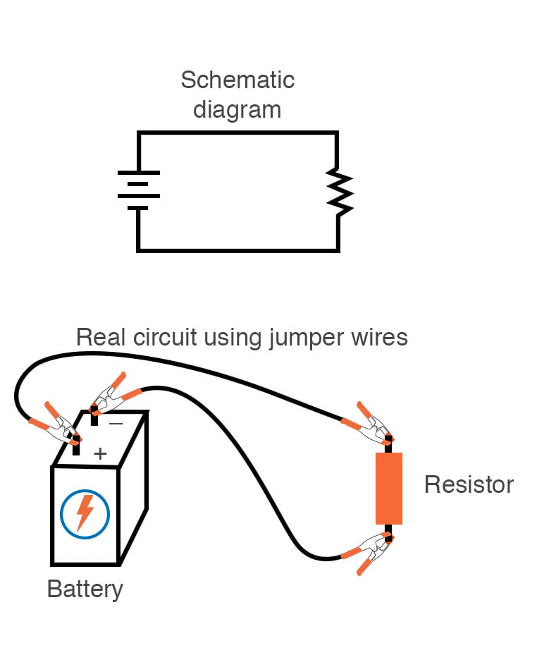
Circuit Diagram Mydraw from www.mydraw.com The pattern of particular interest is the sinusoidal ac waveform for voltage of fig.1. Schematic electrical wiring diagrams are different from other electrical wiring diagrams because they show the flow through the circuit rather than the physical layout of any equipment. There are a myriad of types of circuits —without more specificity or discipline this is impossible to answer in any meaningful way. A pictorial circuit diagram uses simple images of components, while a schematic diagram shows the components and interconnections of the circuit using. These two different types of circuit diagrams are called pictorial (using basic images) or schematic style (using. It is very important to know the basic. Electrical equipment and circuitry is often expressed as symbols and lines that represent the various components and connections within a system. Electric circuits can be further categorized according to their structural features into either an electrical circuit in which some of the elements are connected in series and some of the elements are.
An electrical circuit is a path in which electrons from a voltage or current source flow.
Specialists utilize various kinds of electrical drawings to enlighten a few parts of the framework however the actual circuit and its capacity are as yet unchanged. The electric circuit can be categorized in three different ways. These electrical circuits are addressed by wires to address electrical and electronic parts and lines to address images or symbols. Classification of integrated circuits and their limitation. There are mainly two types of circuit diagrams By santosh das | last updated on november 21, 2019. Explore simple electronics circuits and mini projects ideas. A conductive wire is used to establish relation among source of voltage and load. Electrical diagrams are drawings which are used to represent electrical circuits, these circuits are represented by using lines, symbols, and electrical diagrams show the wiring between components and the relative position of the components. An electric circuit is a closed loop with a continuous flow of electric current from the power supply to the load. An electric circuit is the conductive path for the flow of current is called an electric circuit. An electrical circuit is a closed. The battery has two terminals.
The current diagram represents precisely a physical type of lan topology because it refers to the physical layout of a local network equipment. A conductive wire is used to establish relation among source of voltage and load. An electrical circuit is a closed. Below is a basic set of symbols that you may find on circuit diagrams. The battery has two terminals.
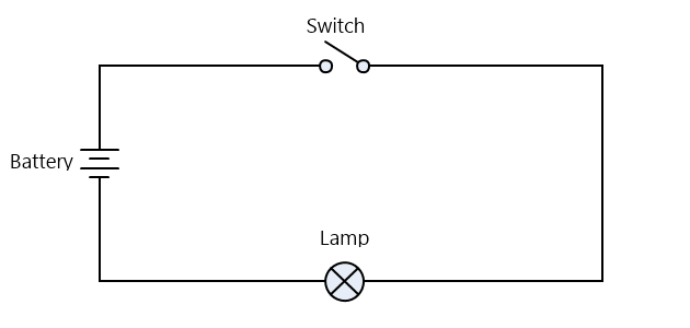
Building Simple Resistor Circuits Series And Parallel Circuits Electronics Textbook from www.allaboutcircuits.com It can be operated at a very high temperature. The pattern of particular interest is the sinusoidal ac waveform for voltage of fig.1. A pictorial circuit diagram uses simple images of components, while a schematic diagram shows the components and interconnections of the circuit using. A series circuit has elements connected in series, or one after the other. An electric circuit is the conductive path for flow of current or electricity is called electric circuit or electrical circuit. The point where those electrons enter an electrical circuit is called the source of electrons. A ladder or line diagram is a diagram that shows the function of an electrical circuit using electrical symbols. The source, the load, and the conductors.
In this article, we are going to explain deeply types of electrical circuits.
Different types of ics are widely applied in our electrical devices such as high power amplifiers, voltage regulators, tv receivers and computers etc. These free electronic circuits are properly tested and can be found with schematic diagrams, breadboard image or pcb, a detailed explanation of working principle and a demonstration video. The battery has two terminals. Electricians depend upon an electric circuit diagram for initiating any building wiring. Types of circuits with diagrams and pdf. Current starts from the positive terminal of the supply, through the line, load, neutral and ends in the negative terminal of the supply. These two different types of circuit diagrams are called pictorial (using basic images) or schematic style (using. A circuit diagram or wiring diagram uses symbols to represent parts of a circuit. Explore simple electronics circuits and mini projects ideas. The interconnection of two or more circuit elements forms an electrical network. A circuit diagram is a visual display of an electrical circuit using either basic images of parts or industry standard symbols. A ladder or line diagram is a diagram that shows the function of an electrical circuit using electrical symbols. An electrical circuit is a closed.
In this article, we are going to explain deeply types of electrical circuits. The electric circuit can be categorized in three different ways. An open circuit does not allow electrical current to flow. The source, the load, and the conductors. These free electronic circuits are properly tested and can be found with schematic diagrams, breadboard image or pcb, a detailed explanation of working principle and a demonstration video.
What Is An Electric Circuit Types Of Circuits Network Parts Of Circuit from www.electricaltechnology.org Electronic circuits are key to designing and defining electronic circuits: Classification of integrated circuits and their limitation. Electrical and electronic circuits can be complicated. In a home electrical circuit, for instance, the same voltage is applied across each light or appliance, but each of these loads draws a different amount two diagrams showing an ammeter connected to a simple circuit in two different positions. An electric circuit is the conductive path for the flow of current is called an electric circuit. An on/ off switch also used between the source and load. Different types of ics are widely applied in our electrical devices such as high power amplifiers, voltage regulators, tv receivers and computers etc. There are mainly two types of circuit diagrams
By santosh das | last updated on november 21, 2019.
It can be operated at a very high temperature. Specialists utilize various kinds of electrical drawings to enlighten a few parts of the framework however the actual circuit and its capacity are as yet unchanged. It is very important to know the basic. In this article, we are going to explain deeply types of electrical circuits. The type of electrical wiring diagram you use depends on what you want to achieve with it. We know that electric current flows in a closed circuit. Different types of ics are widely applied in our electrical devices such as high power amplifiers, voltage regulators, tv receivers and computers etc. The point where the electrons leave an electrical circuit is called the return or earth ground. A circuit diagram or wiring diagram uses symbols to represent parts of a circuit. Symbol usage depends on the audience viewing the diagram. Explaining different types of circuits including series and parallel circuits. Explore simple electronics circuits and mini projects ideas. Circuit elements and types of circuits.