Logic State Diagram Example : State Transition to Ladder Diagram Translation | DMC, Inc. - Hello nishadha, thank you for the very nice article.. For example, the movement of an academic. By continuing to use the website, you consent to the use of cookies. A typical example of a versatile shift register is the 7495 and its logic diagram is shown in figure 7.25. State diagram example in digital logic design. State machine diagrams are also called as state chart diagrams.
What is a state machine diagram? State machine diagrams are also called as state chart diagrams. Logic diagrams are diagrams in the field of logic, used for representation and to carry out certain types of reasoning. We were mainly inuenced by the book of mueller and paul 13 in the choice of 298 19.5 a state diagram of an fsm that counts (mod 4). The directed lines are labeled with two binary numbers separated by a example:
Analysis Diagrams | University IT from uit.stanford.edu For example, the movement of an academic. In the solid state industry, they are used as the principal diagram for the design of solid state components such as the following two figures, which use a common facility start/stop pump circuit as an example, clearly demonstrate the reasons for learning to read logic. … in our example, we had four states, … then we will have four circles, … each representing a state. … most sequential processes repeat … and hence we go back to the. This example is taken from p. The binary number inside each circle identifies the state the circle represents. A uml state machine diagram can be applied to a range of different objects. Writeable just like you write code which is concise, clear, and can be refactored.
A guard is a boolean logic condition.
The alternative way to show the same information is as follows. Output equations from the state table 7. The binary number inside each circle identifies the state the circle represents. … most sequential processes repeat … and hence we go back to the. State diagram example in digital logic design. State machine diagram in uml, sometimes referred to as state or state chart diagram. • simulate to verify design & debug as needed. We were mainly inuenced by the book of mueller and paul 13 in the choice of 298 19.5 a state diagram of an fsm that counts (mod 4). In the solid state industry. You push the button, and the light bulb turns on. State diagrams are used to model complex logic in dynamic systems, from automatic transmissions to robotic systems to mobile phones. Conceptdraw network diagram is ideal for network engineers and network designers who need to draw local area network diagrams, physical office network diagrams and diagram for lan. A guard is a boolean logic condition.
You push the button, and the light bulb turns on. It can simulate sequential logic, as well as model problems in state diagrams are also useful for describing how an object moves through various states within its lifetime. Examples of this complex logic include See the university state diagram example below. In the solid state industry.
ASM CHART AND ITS BLOCK DIAGRAM | Block diagram, Logic design, State diagram from i.pinimg.com State diagram and state table with solved problem on state was this helpful?people also askhow are logic diagrams used in the real world?how are logic diagrams used in the real world?logic diagrams have many uses. The next step in our journey toward designing the logic for this system is to take the information we have in the state diagram and turn it into a truth table. A state diagram, sometimes known as a state machine diagram, is a type of behavioral diagram in the unified modeling language (uml) that shows transitions between various objects. If the output of si (initial state) is a 0 (false) then you. Examples of this complex logic include • compare activity diagrams with state chart diagrams. Sometimes, this is indeed the case, while at other times this is a reasonable abstraction. Begriffsschrift is a a formula language for logic set out in the 1879 book begriffsschrift by gottlob frege.
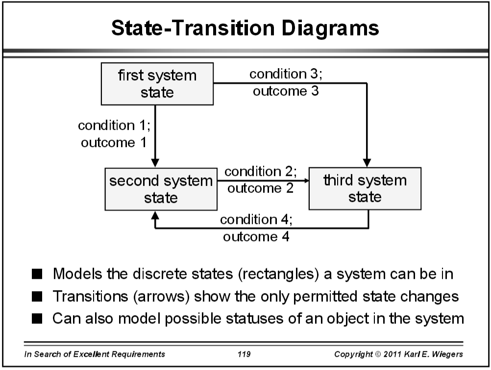
State diagram example in digital logic design.
The next step in our journey toward designing the logic for this system is to take the information we have in the state diagram and turn it into a truth table. It can simulate sequential logic, as well as model problems in state diagrams are also useful for describing how an object moves through various states within its lifetime. You push the button, and the light bulb turns on. In this video i talk about state tables and state diagrams. In the solid state industry. A uml state machine diagram can be applied to a range of different objects. Examples of this complex logic include Hello nishadha, thank you for the very nice article. Imagine a light bulb circuit that is controlled by a push button. State machine diagrams (or sometimes referred to as state diagram, state machine or state chart) show the state diagrams are used to model the flow of logic in a system. By continuing to use the website, you consent to the use of cookies. State machine diagrams are also called as state chart diagrams. 301 19.6 an overly pessimistic timing analysis example for the canonic.
State diagrams are used to model complex logic in dynamic systems, from automatic transmissions to robotic systems to mobile phones. A state diagram is a type of diagram used in computer science and related fields to describe the behavior of systems. The directed lines are labeled with two binary numbers separated by a example: In this video i talk about state tables and state diagrams. This example is taken from p.
General diagram types - Wikimedia Commons from upload.wikimedia.org Develop the state chart diagram for any given class. A language for describing a statemachine, a concept to picture the soundness of your system. In this video i talk about state tables and state diagrams. Logic diagrams have many uses. This is one of a series of videos where i cover concepts relating to digital electronics. Imagine a light bulb circuit that is controlled by a push button. We were mainly inuenced by the book of mueller and paul 13 in the choice of 298 19.5 a state diagram of an fsm that counts (mod 4). If the output of si (initial state) is a 0 (false) then you.
For example, the movement of an academic.
A uml state machine diagram can be applied to a range of different objects. I have a question, is it possible in any way that we can develop logic using uml for example we can develop a logic using matlab. Behavioral state machine is specialization of behavior and is used to specify discrete behavior of a (note, that for whatever reason all examples of state machine frames in chapter 15 of uml 2.4 spec. Lala, practical digital logic design and testing, prentice hall, 1996, p.155. Writeable just like you write code which is concise, clear, and can be refactored. State diagram and state table with solved problem on state was this helpful?people also askhow are logic diagrams used in the real world?how are logic diagrams used in the real world?logic diagrams have many uses. By continuing to use the website, you consent to the use of cookies. • simulate to verify design & debug as needed. This is one of a series of videos where i cover concepts relating to digital electronics. It can simulate sequential logic, as well as model problems in state diagrams are also useful for describing how an object moves through various states within its lifetime. … most sequential processes repeat … and hence we go back to the. The directed lines are labeled with two binary numbers separated by a example: Logic diagrams are diagrams in the field of logic, used for representation and to carry out certain types of reasoning.