Home
› Light Switch Loop Wiring Diagram - Wiring Diagram For A One Way Lighting Circuit Using The 3 Plate Method Connections Explained Youtube : Instead of pulling a cord every time you want to turn the light on or off, you flip a switch.
Light Switch Loop Wiring Diagram - Wiring Diagram For A One Way Lighting Circuit Using The 3 Plate Method Connections Explained Youtube : Instead of pulling a cord every time you want to turn the light on or off, you flip a switch.
Light Switch Loop Wiring Diagram - Wiring Diagram For A One Way Lighting Circuit Using The 3 Plate Method Connections Explained Youtube : Instead of pulling a cord every time you want to turn the light on or off, you flip a switch.. When using this method, the home run wire goes to the first fixture, other fixtures are then daisy chained while maintaining wire polarity (very important). A switch loop is created when power is fed to a light fixture and the hot wire is broken and extended to a light switch. The loop at the switch method for wiring is more commonly used in the uk than in australia, however it can still be found in some homes within australia. You may find that there are only a few wires in your ceiling rose. With easy to follow diagrams and instructions, you can have that convenience in no time.
Does it matter which wire goes where on a light switch? Next, the incoming white neutral wire is attached to the light fixture, as usual, and the black wire from the switch is connected to the light. The loop method brings the same voltage and power to both ends of the wire run. In layman's terms, a switch loop is another term for a wiring circuit created to connect a light fixture to a wall switch. Understanding how the switch is wired is the most important part.
How To Wire A Light Switch And Outlet In The Same Box Quora from qph.fs.quoracdn.net A switch loop is created when power is fed to a light fixture and the hot wire is broken and extended to a light switch. In layman's terms, a switch loop is another term for a wiring circuit created to connect a light fixture to a wall switch. Light circuit phase to the c terminal on the other switch. Need help wiring a 3 way switch? The 'light' cable goes to the light fitting. Tape the loop temporarily to outside of rail to prevent it being pulled back in. Common connects only to 1 in switch position on common connects only to 2 in switch position off nothing connects to the loop terminal in the switch. The principle is exactly the same as when looping at the ceiling rose or using a junction box.
To make a switch loop, connect the incoming hot (black) wire to the white neutral wire that runs to the switch.
A switch loop is created when power is fed to a light fixture and the hot wire is broken and extended to a light switch. To make a switch loop, connect the incoming hot (black) wire to the white neutral wire that runs to the switch. Pull red wire loops 2 2.1 at the last hole before the end of circuit, use a wire hook to gently pull out 100mm length of red feed wire from the hole to create your first loop. It is a modern way of wiring which reduces breaks in the cable and makes the work much easier and faster. The principle behind this type of wiring is similar to that used in the previous method, in that the cable supplies power from one light to the unit. Another common method of wiring is known as the loop method. Mar 09, 21 09:56 pm. Ceiling fan diagram (switch loop) this ceiling fan wiring diagram can be used if the power source is supplied to the fan fixture. The 'in' cable supplies power from the previous light or consumer unit. This shows wiring a light switch when the power comes into the light outlet first. Step by step instructions on how to wire a switched outlet. You may find that there are only a few wires in your ceiling rose. Sometimes it is handy to have an outlet controlled by a switch.
Ceiling fan diagram (switch loop) this ceiling fan wiring diagram can be used if the power source is supplied to the fan fixture. The 'loop' terminal on the wall switch is utilised when multiple switches are used to operate the lights in one light circuit. There is no guarantee that the switch would have been wired originally with the live feed phase to the c (common) terminal. For new wiring, you would run a three wire cable and use the red and black for the loop and leave the white unused and capped in the switch box. When using this method, the home run wire goes to the first fixture, other fixtures are then daisy chained while maintaining wire polarity (very important).
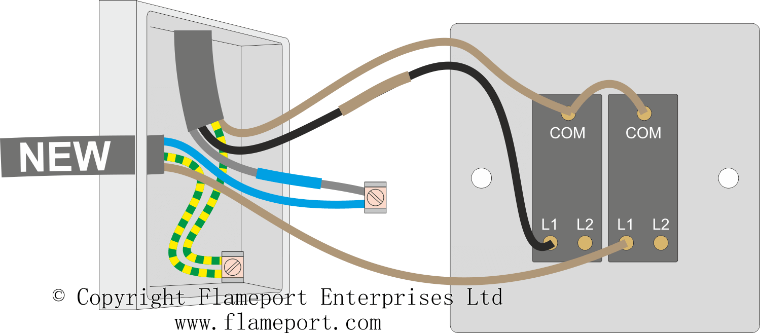
Adding An Extra Light From A Light Switch from www.flameport.com A metal light switch must be earthed as seen below. There is no guarantee that the switch would have been wired originally with the live feed phase to the c (common) terminal. A flush fitting wall box is sunk into the wall to take the switch, or alternatively a surface mounted box is fitted. Need help wiring a 3 way switch? The loop method brings the same voltage and power to both ends of the wire run. This circuit diagram shows the wiring for a new receptacle outlet connected at an existing light fixture where the source hot is at the ceiling box. This switch body does have two isolated negative inputs (t9 and t7) for each lamp or led in the switch. Video explains the connection required within.
The principle is exactly the same as when looping at the ceiling rose or using a junction box.
Ceiling fan diagram (switch loop) this ceiling fan wiring diagram can be used if the power source is supplied to the fan fixture. Sometimes it is handy to have an outlet controlled by a switch. A switch loop is created when power is fed to a light fixture and the hot wire is broken and extended to a light switch. When using this method, the home run wire goes to the first fixture, other fixtures are then daisy chained while maintaining wire polarity (very important). Notice on the wiring diagram that of the 10 prongs (spade connectors, called termianls) on the back, four 4 make the rocker switch lights function, while the remaining six are used for the electromechanical switching contacts. If you are using metal light switches (fig 5) make. Understanding how the switch is wired is the most important part. What is a switch loop diagram? The principle is exactly the same as when looping at the ceiling rose or using a junction box. It shows the components of the circuit as simplified shapes, and the power and signal connections amid the devices. Instead of pulling a cord every time you want to turn the light on or off, you flip a switch. Let's break down the wiring to steps. Or push a button to activate the light.
This page contains wiring diagrams for household light switches and includes: Need help wiring a 3 way switch? The principle behind this type of wiring is similar to that used in the previous method, in that the cable supplies power from one light to the unit. The loop terminals have no involvement in the switching process, just a connection for the neutrals. Common connects only to 1 in switch position on common connects only to 2 in switch position off nothing connects to the loop terminal in the switch.
Two Way Switching Explained How To Wire 2 Way Light Switch Realpars from realpars.com Another common method of wiring is known as the loop method. The loop at the switch method. The 'loop' terminal on the wall switch is utilised when multiple switches are used to operate the lights in one light circuit. The 'light' cable goes to the light fitting. Sometimes it is handy to have an outlet controlled by a switch. The loop terminal allows for either switch in the loop to turn the lights on or off at each point. Figure 3 shows the wiring configuration using 14/3 wire in a switch loop. The principle behind this type of wiring is similar to that used in the previous method, in that the cable supplies power from one light to the unit.
When using this method, the home run wire goes to the first fixture, other fixtures are then daisy chained while maintaining wire polarity (very important).
The 'loop' terminal on the wall switch is utilised when multiple switches are used to operate the lights in one light circuit. The first thing we need to understand is how to wire a light pendant. Step by step instructions on how to wire a switched outlet. The (l2) terminal is unused. The loop at the switch method. You may find that there are only a few wires in your ceiling rose. The principle is exactly the same as when looping at the ceiling rose or using a junction box. Sometimes it is handy to have an outlet controlled by a switch. The principle behind this type of wiring is similar to that used in the previous method, in that the cable supplies power from one light to the unit. For example, you have multiple entrances into a kitchen, placing a light switch at each entrance negates the need to cross a dark room to reach the single light switch; With that said, this electrical tutorial presents a guide to identifying the switched live wire on a lighting circuit and also explains how to rewire a ceiling rose. Instead of pulling a cord every time you want to turn the light on or off, you flip a switch. A flush fitting wall box is sunk into the wall to take the switch, or alternatively a surface mounted box is fitted.