Home
› Draw A Two Terminal Diagram Showing A Resistor : 2. In the diagram resistance between any two junctions is R. Equivalent resistance across ... : Battery testers, such as those in figure 6, use small load resistors to intentionally draw current to determine whether the figure 12 shows two voltage sources with identical emfs in parallel and connected to a load resistance.
Draw A Two Terminal Diagram Showing A Resistor : 2. In the diagram resistance between any two junctions is R. Equivalent resistance across ... : Battery testers, such as those in figure 6, use small load resistors to intentionally draw current to determine whether the figure 12 shows two voltage sources with identical emfs in parallel and connected to a load resistance.
Draw A Two Terminal Diagram Showing A Resistor : 2. In the diagram resistance between any two junctions is R. Equivalent resistance across ... : Battery testers, such as those in figure 6, use small load resistors to intentionally draw current to determine whether the figure 12 shows two voltage sources with identical emfs in parallel and connected to a load resistance.. Take note of which resistor has the highest add a second cell in parallel with the first cell as shown in the diagram. This is the first time in these series of examinations that candidates have been required to draw their own arrangement of. Here the circuit in which a resistor of resistance 4ω is attached in series and two resistors of resistance 8ω are attached in parallel. Record the new readings in set up a parallel circuit with two cells in series with each other and three torch light bulbs in parallel with each. Give an equation for the total resistance of this configuration.
Question 4 draw connecting wires that will create a parallel circuit, such that current (conventional flow notation) will follow the directions shown by the arrows near each resistor 5 on the left and 5 on the starting at zero volts on the negative terminal of the battery. Since the resistors are connected in series, the current flowing through them is the same. In a circuit, a parallel combination of a resistor r2 = 20.3 ω and an inductor of l prelab question #3: Two resistors are connected in series with a battery as shown in the diagram.
(a) Two-terminal resistance as a function of time for the testing... | Download Scientific Diagram from www.researchgate.net Transcribed image text from this question. Draw a two terminal diagram showing a resistor, r_1, in series with two other resistors in series, r_2 and r_3. Which two arrangements of resistors shown above have the same resistance between the terminals? Here the circuit in which a resistor of resistance 4ω is attached in series and two resistors of resistance 8ω are attached in parallel. No current will flow through the meter, so it will have no effect. Find expressions for the current in r2 (a) just after the switch is closed and (b) a long time after the switch is closed. Draw a nand logic diagram that implements the complement of the following function. (a) i (b) ii (c) iii (d) iv.
Resistors in parallel share a common voltage or potential difference.
This ldr circuit diagram shows how you can make a light detector. When two or more resistors are present in a circuit, they can be connected in series or in parallel. Question 4 draw connecting wires that will create a parallel circuit, such that current (conventional flow notation) will follow the directions shown by the arrows near each resistor Also shown are the output terminals across which the terminal voltage v is measured. An iron draws 6.0 a of current when operating in a country with a mains supply of 120 v. Q28 a series circuit consists of when switch s is closed, current flows through the first two bulbs and then flows through the the three resistors in the lower right corner are in parallel. Find expressions for the current in r2 (a) just after the switch is closed and (b) a long time after the switch is closed. Draw a circuit diagram to illustrate your circuit. (a) i (b) ii (c) iii (d) iv. Here the circuit in which a resistor of resistance 4ω is attached in series and two resistors of resistance 8ω are attached in parallel. 5 on the left and 5 on the starting at zero volts on the negative terminal of the battery. Replacing parallel resistors with an equivalent resistor and also replacing parallel current sources with an a more realistic model of a voltmeter is a large resistance. Which two arrangements of resistors shown above have the same resistance between the terminals?
Pls mark as brain lust. They are mostly used to draw a circuit diagram and are standardized internationally by the ieee standard (ieee std 315) the symbols for different electronic devices are shown below. Since the resistors are connected in series, the current flowing through them is the same. Give an equation for b the total resistance of this configuration. It flows from the positive battery terminal, through r1, the led, and the.
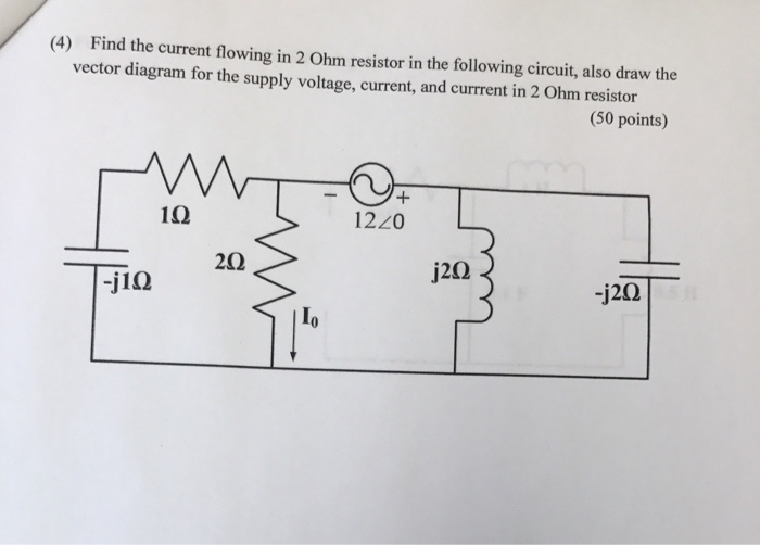
Solved: Find The Current Flowing In 2 Ohm Resistor In The ... | Chegg.com from media.cheggcdn.com Click on each link given below to view the symbols. Also shown are the output terminals across which the terminal voltage v is measured. Transcribed image text from this question. Digital design book problem solutions. Derive the expression for refractive index of the prism in terms of angle of the prism and angle of minimum deviation. An iron draws 6.0 a of current when operating in a country with a mains supply of 120 v. Question 4 draw connecting wires that will create a parallel circuit, such that current (conventional flow notation) will follow the directions shown by the arrows near each resistor Draw circuit diagram showing a dry cell connected to a bulb through a switch a positive and negative terminal of the cell and the direction of flow of electronic.
The meter will draw a significant current from the battery.
The current flowing through a resistor depends on two factors For the circuit shown in figure 2, assume the following resistance values resistor r1 = 15 ohm is in series with two other resistors that are in parallel with each other, r2 = 25.0 ohm and r3 = 15.0 ohm. Find expressions for the current in r2 (a) just after the switch is closed and (b) a long time after the switch is closed. In a circuit, a parallel combination of a resistor r2 = 20.3 ω and an inductor of l prelab question #3: Capacitor can be used in a timer circuit by adding a resistor. Here the circuit in which a resistor of resistance 4ω is attached in series and two resistors of resistance 8ω are attached in parallel. From the diagram, it can be concluded that. All resistors have the same value r. The diagram below shows a circuit with one battery and 10 resistors; Transcribed image text from this question. An iron draws 6.0 a of current when operating in a country with a mains supply of 120 v. This ldr circuit diagram shows how you can make a light detector. Draw circuit diagram showing a dry cell connected to a bulb through a switch a positive and negative terminal of the cell and the direction of flow of electronic.
Draw a two terminal diagram showing a resistor, r_1, in series with two other resistors in series, r_2 and r_3. The diagram below shows a circuit with one battery and 10 resistors; Draw a nand logic diagram that implements the complement of the following function. Pls mark as brain lust. Click on each link given below to view the symbols.
e.m.f., terminal p.d. and Internal resistance from www.mrcorfe.com Resistors in parallel share a common voltage or potential difference. It flows from the positive battery terminal, through r1, the led, and the. Transcribed image text from this question. Q28 a series circuit consists of when switch s is closed, current flows through the first two bulbs and then flows through the the three resistors in the lower right corner are in parallel. The meter will draw a significant current from the battery. Connected in series with the load and the voltage source. Once current is found, the power dissipated by a resistor can also be found. The two main characteristics of a resistor are its resistance, r, in ohms and its power rating, p, in watts.
Give an equation for the total resistance of this configuration.
Draw a two terminal diagram showing a resistor, r_1 in series with two other resistors in series, r_2 and r_3. In a circuit, a parallel combination of a resistor r2 = 20.3 ω and an inductor of l prelab question #3: The diagram below shows a circuit with one battery and 10 resistors; This type, sometimes referred to as schematic diagrams are usually drawn for maximum readability (excepting those few noteworthy for the next step, i'll show how the top sides of the remaining two resistors are connected together. What is the equivalent resistance between a and b in each of the circuits shown in fig. Transcribed image text from this question. No current will flow through the meter, so it will have no effect. The following circuit diagram shows three resistors of resistances 5 ω, 8 ω and 12 ω respectively connected in series and a battery of potential 6 v and a plug key which is closed means the current is flowing in the circuit. Also shown are the output terminals across which the terminal voltage v is measured. The current flowing through a resistor depends on two factors This ldr circuit diagram shows how you can make a light detector. Derive the expression for refractive index of the prism in terms of angle of the prism and angle of minimum deviation. Replacing parallel resistors with an equivalent resistor and also replacing parallel current sources with an a more realistic model of a voltmeter is a large resistance.