Home
› Wire Diagram Thermostat / How to Wire an Air Conditioner for Control - 5 Wires / The 18 refers to the gauge and when i attach new thermostat it does not power up.
Wire Diagram Thermostat / How to Wire an Air Conditioner for Control - 5 Wires / The 18 refers to the gauge and when i attach new thermostat it does not power up.
Wire Diagram Thermostat / How to Wire an Air Conditioner for Control - 5 Wires / The 18 refers to the gauge and when i attach new thermostat it does not power up.. Installing your ecobee thermostat with a c wire. Rh c rc y z y2 w2 g. Wiring a thermostat is a simple step by step process that anyone can do. This video contains 10 wiring diagrams. This is commonly found in standard hvac systems that use an air conditioner and a furnace.
We address them in order from most common to least common. Here is the last bit of theory before we get down to thermostat wiring example 2. I think the blue wire in the diagram comes out. When working with a thermostat the cover can be snapped off to expose the wiring. Wiring a thermostat is a simple step by step process that anyone can do.
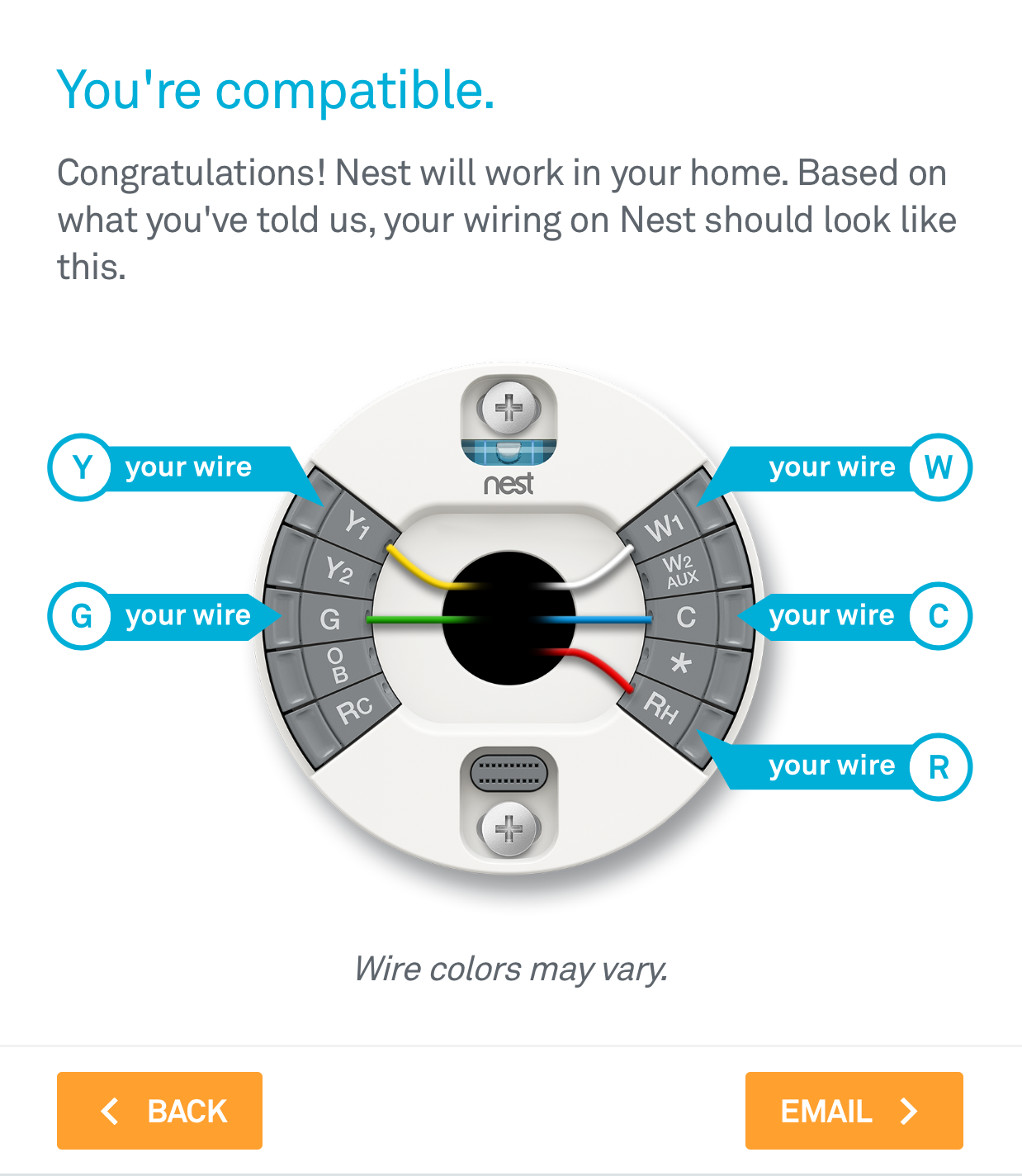
Nest thermostat 3rd Generation Wiring Diagram | Free Wiring Diagram from ricardolevinsmorales.com Heat pump systems wiring diagrams: Diagrams are available for all. Connect the wires to your nest thermostat's base by following the wiring diagram that you got from. How to wire a thermostat. Terminal outputs and wiring diagrams. Conventional heating/cooling systems wiring diagrams: Rh c rc y z y2 w2 g. Voltage divider circuit is formed by the thermistor and a variable resistor.
There are just two things.
Voltage divider circuit is formed by the thermistor and a variable resistor. Wall plate for a 4 wire smart thermostat installation. Thermostat installation & wiring diagrams. Diagrams are available for all. I think the blue wire in the diagram comes out. This is commonly found in standard hvac systems that use an air conditioner and a furnace. Conventional heating/cooling systems wiring diagrams: Wiring a thermostat is a simple step by step process that anyone can do. Rh c rc y z y2 w2 g. The nest thermostat doesn't need them. We address them in order from most common to least common. The 18 refers to the gauge and when i attach new thermostat it does not power up. This video contains 10 wiring diagrams.
This information is designed to help you understand the. Heat pump systems wiring diagrams: Diagrams are available for all. A line voltage thermostat will typically have wires larger than 18 gauge and may not have. Furnace thermostat wiring falls in the diy category that a handy type person can hook up or fix.
How To: Install The Nest Thermostat | The Craftsman Blog from thecraftsmanblog.com We address them in order from most common to least common. Conventional heating/cooling systems wiring diagrams: A line voltage thermostat will typically have wires larger than 18 gauge and may not have. The thermostat wiring on these systems can have very similar wiring properties. Rh c rc y z y2 w2 g. When working with a thermostat the cover can be snapped off to expose the wiring. Look for a wire connected to a terminal labeled with a c on the thermostat. This is commonly found in standard hvac systems that use an air conditioner and a furnace.
Conventional heating/cooling systems wiring diagrams:
Most of the process is about following safety procedures and avoiding common mistakes. This is commonly found in standard hvac systems that use an air conditioner and a furnace. Installing your ecobee thermostat with a c wire. Wall plate for a 4 wire smart thermostat installation. Look for a wire connected to a terminal labeled with a c on the thermostat. Diagrams are available for all. The above is a typical wiring diagram of a nest thermostat with 4 wires. It shows how the electrical wires are interconnected and can also show. There are just two things. The thermostat wiring on these systems can have very similar wiring properties. When working with a thermostat the cover can be snapped off to expose the wiring. Thermostat installation & wiring diagrams. Nest thermostat connectors wiring diagrams:
This information is designed to help you understand the. This thermostat circuit compromises of a voltage divider circuit and output on and off switching circuit. The thermostat wiring on these systems can have very similar wiring properties. I think the blue wire in the diagram comes out. Red wire = rh = power.
Honeywell Thermostat Wiring Diagram 4 Wire | Tom's Tek Stop from i2.wp.com A wiring diagram is a simple visual representation of the physical connections and physical layout of an electrical system or circuit. This thermostat circuit compromises of a voltage divider circuit and output on and off switching circuit. Honeywell thermostat wiring diagram 4 wire. The 18 refers to the gauge and when i attach new thermostat it does not power up. Wiring a thermostat is a simple step by step process that anyone can do. There are just two things. A line voltage thermostat will typically have wires larger than 18 gauge and may not have. Wall plate for a 4 wire smart thermostat installation.
Diagrams are available for all.
This is a slightly more complicated case. Red wire = rh = power. I think the blue wire in the diagram comes out. Supervision is needed by a licensed hvacr tech while doing this as experience. Gives honeywell thermostat wiring diagram 4 wire guides and hints. Heat pump systems wiring diagrams: This thermostat circuit compromises of a voltage divider circuit and output on and off switching circuit. See the diagram below for what each wire controls on your system This video contains 10 wiring diagrams. Honeywell thermostat wiring diagram 4 wire. Wall plate for a 4 wire smart thermostat installation. Sensi thermostat wiring diagram | free wiring diagram. Diagrams are available for all.