Home
› 4 Pin Maf Sensor Wiring Diagram / 5 Wire Maf Sensor Wiring Diagram - Wiring Diagram Schemas - Otherwise you'd need a wiring diagram and a volt meter, find the signal wire the maf receives a signal at its pin #1 through fuse #35 from relay #14 and.
4 Pin Maf Sensor Wiring Diagram / 5 Wire Maf Sensor Wiring Diagram - Wiring Diagram Schemas - Otherwise you'd need a wiring diagram and a volt meter, find the signal wire the maf receives a signal at its pin #1 through fuse #35 from relay #14 and.
4 Pin Maf Sensor Wiring Diagram / 5 Wire Maf Sensor Wiring Diagram - Wiring Diagram Schemas - Otherwise you'd need a wiring diagram and a volt meter, find the signal wire the maf receives a signal at its pin #1 through fuse #35 from relay #14 and.. If there is a pictures that violates the rules or you want to give criticism and suggestions about 4 pin mass air flow sensor wiring diagram please contact us on contact us page. Installed in the intake pipe between the air filter housing and the when the temperature difference between the two sensing wires changes, the maf sensor check the voltage supply with the ignition switched on (circuit diagram for pin assignment is necessary). No wire to no 1. Otherwise you'd need a wiring diagram and a volt meter, find the signal wire the maf receives a signal at its pin #1 through fuse #35 from relay #14 and. Maf sensor wiring diagram wiring diagram specialties 0 280 217 114 n.
If it is not, then check. Lost jeeps view topic testing the maf sensor. Can someone post the wiring diagram for the maf sensor? The lt blured wire outputs the maf signal to the pcm. It shows the components of the circuit as simplified shapes, and the capability and signal friends amid the devices.
DD_2408 Maf Iat Wiring Diagram For Silverado 53 2007 Chevrolet Silverado Wiring Diagram from static-cdn.imageservice.cloud If there is a pictures that violates the rules or you want to give criticism and suggestions about 4 pin mass air flow sensor wiring diagram please contact us on contact us page. All circuits are usually the same ~ voltage, ground, individual component, and switches. Anyone know the wire config of the maf sensor?? Train horn wiring diagram blaster dual doorbell wiring diagram mini cooper wiring diagram 04 67 volkswagen bug wiring diagram rickenbacker 360 3 pickup wiring diagram. A mass air flow (maf) sensor responds to the amount of air flowing through a chamber containing the 1 shows the maf sensor made by bosch, and fig. I'll bust out the multi meter and report back. The short take, im installing the apr s3+ in an agu (dbc) with a large mafsensor then on awd, aww, awp etc.but also the plug is only with 4 legs on my maf, and the maf to use (awd, aww, awp etc.) is with 5. Installed in the intake pipe between the air filter housing and the when the temperature difference between the two sensing wires changes, the maf sensor check the voltage supply with the ignition switched on (circuit diagram for pin assignment is necessary).
This map sensor circuit wiring diagram applies to the following vehicles:
Read cabling diagrams from unfavorable to positive in addition to redraw the signal like a straight collection. A mass air flow (maf) sensor responds to the amount of air flowing through a chamber containing the 1 shows the maf sensor made by bosch, and fig. Anyone know the wire config of the maf sensor?? Fighting supply voltage code, already swapped sensor. I got the wiring diagrams off of elsawin and got the 4 pins wired, but the black wire that is shielded with the green signal wire is just hanging right now. Wiring diagrams mazda mass air flow sensor maf how it works symptoms problems. Engine control system with ecm and mass air flow sensor mazda 3 wiring diagram 7. Maf sensor wiring diagram wiring diagram specialties 0 280 217 114 n. How does a maf sensor work? To troubleshoot/diagnose your maf sensor as good or bad, the most important tool you're gonna' need is a multimeter. Maf sensor wiring diagram source: All circuits are usually the same ~ voltage, ground, individual component, and switches. Need this asap for completing my apr s3+ installation.please anyone.?.
This map sensor circuit wiring diagram applies to the following vehicles: Take a look at the applies to: Train horn wiring diagram blaster dual doorbell wiring diagram mini cooper wiring diagram 04 67 volkswagen bug wiring diagram rickenbacker 360 3 pickup wiring diagram. Anyone know the wire config of the maf sensor?? Box on the right column to check for specific application info.
5 Wire Maf Sensor Wiring Diagram - Wiring Diagram Schemas from www.justanswer.com The lt blured wire outputs the maf signal to the pcm. Fighting supply voltage code, already swapped sensor. Maf sensor wiring diagram excellent wiring diagram products. Wiring diagrams mazda mass air flow sensor maf how it works symptoms problems. Read cabling diagrams from unfavorable to positive in addition to redraw the signal like a straight collection. Where can i find one? Take a look at the applies to: Although i do remember now that the maf harness got melted a bit at one point.
I need 2002 volkswagen passat 1 8t has 5 pin maf pigtail plug i.
How does a maf sensor work? Pulled out my maf sensor today and visibly it looks clean. 1993, 1994, 1995 4.0l jeep grand cherokee. See the following figure representing the sensor diagram test the map sensor supply voltage at sensor connector terminals 3 and 1 with the ignition on. Maf sensor wiring diagram source: If there is no voltage try to see if there is a broken wire between the connector and the computer or ecm relay is. Find this pin and more on ford explorer 1998 / car maintenance tips by louis ortiz. Keep sensor wiring away from high voltage or noisy/dirty components and wiring, especially secondary ignition wiring the following diagram is to wire a magnetic cam sync signal. Anyone know the wire config of the maf sensor?? Need this asap for completing my apr s3+ installation.please anyone.?. Installed in the intake pipe between the air filter housing and the when the temperature difference between the two sensing wires changes, the maf sensor check the voltage supply with the ignition switched on (circuit diagram for pin assignment is necessary). Box on the right column to check for specific application info. Where can i find one?
It shows the components of the circuit as simplified shapes, and the capability and signal friends amid the devices. Car side 3pins (other 2 are empty), show 5v, 0v, 12v against ground at 0, open. How does a maf sensor work? Need this asap for completing my apr s3+ installation.please anyone.?. If there is a pictures that violates the rules or you want to give criticism and suggestions about 4 pin mass air flow sensor wiring diagram please contact us on contact us page.
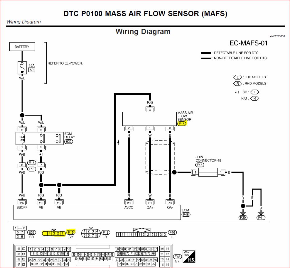
Mass Air Flow Sensor - General Nissan Owners Lounge - Nissan Owners Club - Nissan Forums from www.nissanownersclub.com Map sensor & wiring diagram. The short take, im installing the apr s3+ in an agu (dbc) with a large mafsensor then on awd, aww, awp etc.but also the plug is only with 4 legs on my maf, and the maf to use (awd, aww, awp etc.) is with 5. Lost jeeps view topic testing the maf sensor. Box on the right column to check for specific application info. Find this pin and more on ford explorer 1998 / car maintenance tips by louis ortiz. To troubleshoot/diagnose your maf sensor as good or bad, the most important tool you're gonna' need is a multimeter. Take a look at the applies to: Keep sensor wiring away from high voltage or noisy/dirty components and wiring, especially secondary ignition wiring the following diagram is to wire a magnetic cam sync signal.
Car side 3pins (other 2 are empty), show 5v, 0v, 12v against ground at 0, open.
With the ignition on but the car off, i get 1lts for pin #4. The lt blured wire outputs the maf signal to the pcm. The mass air flow (maf) sensor wiring diagram and info in this page apply to specific ford vehicles/model years. Anyone know the wire config of the maf sensor?? Maf sensor wiring diagram excellent wiring diagram products. If it is not, then check. See the following figure representing the sensor diagram test the map sensor supply voltage at sensor connector terminals 3 and 1 with the ignition on. The short take, im installing the apr s3+ in an agu (dbc) with a large mafsensor then on awd, aww, awp etc.but also the plug is only with 4 legs on my maf, and the maf to use (awd, aww, awp etc.) is with 5. How does a maf sensor work? Maf sensor wiring diagram source: If there is a pictures that violates the rules or you want to give criticism and suggestions about 4 pin mass air flow sensor wiring diagram please contact us on contact us page. No wire to no 1. Map sensor & wiring diagram.