Wiring Schematic Symbol Chart - Automotive Wiring Schematic Symbols Pdf - Wiring Diagram ... : This will help you figure out what's.. Ohm's law, resistor color code, circuit symbols poster | zazzle.com. Limit switch legend aov schematic (with block included) wiring (or connection) diagram wiring (or connection) diagram tray & conduit layout drawing embedded conduit. Conductors used to connect different components. You will see the symbol for a resistor. Complete circuit symbols of electronic components.
Artistic poster of various electronic symbols. The charts below will help you to understand what everything on an. Electrical schematic symbol wiring conductors not joined conductors joined shielded wire or coaxial cable terminal address or data bus multiple conductor electrical schematic symbol wiring. Schematic symbols for an atmega328 microcontroller (commonly found on arduinos), an atsha204 encryption ic, and an attiny45 mcu. Wires would all be in contact.
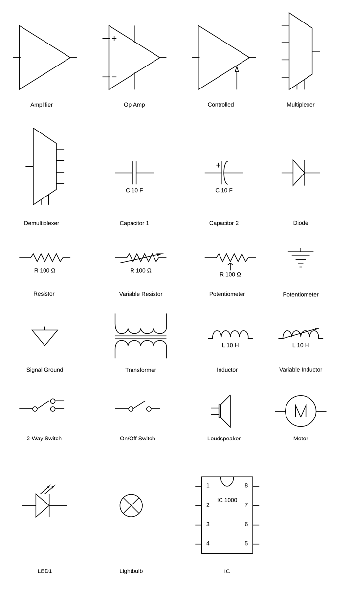
Circuit Diagram Symbols | Lucidchart from d2slcw3kip6qmk.cloudfront.net Electronics symbols for schematics and wiring diagrams are mostly universal with a few of the symbols that may look different if reading other types of schematics. A 'blob' should be drawn where wires are connected (joined), but it is sometimes omitted. The charts below will help you to understand what everything on an. 01_b_r03 electrical basics drawing index. Electrical symbols on wiring and schematic diagrams. But which do you use when creating connections between your symbols? Electrical symbols and electronic circuit symbols are used for drawing schematic diagram. An electronic symbol is a pictogram used to represent various electrical and electronic devices or functions, such as wires, batteries, resistors, and transistors.
Electrical symbols on wiring and schematic diagrams.
Normally automotive wiring diagram symbols refers to electrical schematic or circuits diagram. Switch symbols and relay symbols. Most symbols used on a wiring diagram look like abstract versions of the real objects they represent. Your walls are a reflection of your personality, so let them speak with your favorite quotes, art, or designs printed on our custom posters! Electrical symbols on wiring and schematic diagrams. The article also contains the purpose and benefits of creating a type of wiring diagram wiring diagram vs schematic diagram how to read a wiring diagram: Electrical schematic symbols names and identifications. Every connection point has a sequence number that uniquely identifies it. Circuit symbols are used in circuit diagrams (schematics) to represent electronic components. Complete circuit symbols of electronic components. All circuit symbols are in standard format and can be used for drawing schematic circuit diagram and layout. 01_b_r03 electrical basics drawing index. Electrical schematic symbol wiring conductors not joined conductors joined shielded wire or coaxial cable terminal address or data bus multiple conductor electrical schematic symbol wiring.
You do want to use the net icon to wire up your schematic symbols. Ec24 wiring schematic symbols chart basic electronics. Standard electrical jic / nfpa symbols used to represent contactors, thermal overloads, motors and transformers for usage in electrical schematic diagrams. Every connection point has a sequence number that uniquely identifies it. The charts below will help you to understand what everything on an.
Hvac Wiring Schematic Diagram Symbols - Wiring Forums from i1.wp.com Electrical schematic symbols names and identifications. Read how to draw a circuit diagram. The wiring diagram connection point must have the same value as the corresponding connection point in the schematic. Schematic symbols chart | schematic symbols schematic. Normally automotive wiring diagram symbols refers to electrical schematic or circuits diagram. Complete circuit symbols of electronic components. Learn about wiring diagram symbools. Use this chart for your own personal use completely free.
Terms in this set (16).
Electronics symbols for schematics and wiring diagrams are mostly universal with a few of the symbols that may look different if reading other types of schematics. One of the first things you need to learn when it comes to performing diy repairs is how to read a wiring schematic. Symbols you should know wiring diagram. Switch symbols and relay symbols. Sometimes wiring diagram can also refer to the architectural. The wiring diagram connection point must have the same value as the corresponding connection point in the schematic. All circuit symbols are in standard format and can be used for drawing schematic circuit diagram and layout. As you go through various parallax microcontroller tutorials, you will see schematics describing the circuits to be built. 01_b_r03 electrical basics drawing index. Circuit diagrams chart answer key introduction road signs are good examples of recognizable symbols. Note that all these links are external and we cannot provide support on the circuits or offer any guarantees to their accuracy. A 'blob' should be drawn where wires are connected (joined), but it is sometimes omitted. The last circuit was added on thursday, november 28, 2019.please note some adblockers will.
Electrical components chart bedowntowndaytona com. Complete circuit symbols of electronic components. Every connection point has a sequence number that uniquely identifies it. Unconnected wires wires cross without connecting. You will see the symbol for a resistor.
Twisted Wire Schematic Symbol - Wiring Diagram from strategiccontentmarketing.co Terms in this set (16). Conductors used to connect different components. Most symbols used on a wiring diagram look like abstract versions of the real objects they represent. Note that all these links are external and we cannot provide support on the circuits or offer any guarantees to their accuracy. A schematic shows the plan and function for an electrical circuit, but is not concerned with the physical layout of the wires. Schematics also illustrate how the different components are connected using circuit diagrams. Read how to draw a circuit diagram. This printable pdf chart can be viewed, downloaded and also printed.
The wiring diagram connection point must have the same value as the corresponding connection point in the schematic.
Schematics also illustrate how the different components are connected using circuit diagrams. Schematic symbols chart | schematic symbols schematic. Use this chart for your own personal use completely free. There are two kinds of wires in autodesk eagle, the standard wire, and the net. The article also contains the purpose and benefits of creating a type of wiring diagram wiring diagram vs schematic diagram how to read a wiring diagram: There are 2777 circuit schematics available. As you go through various parallax microcontroller tutorials, you will see schematics describing the circuits to be built. A schematic shows the plan and function for an electrical circuit, but is not concerned with the physical layout of the wires. A 'blob' should be drawn where wires are connected (joined), but it is sometimes omitted. Limit switch legend aov schematic (with block included) wiring (or connection) diagram wiring (or connection) diagram tray & conduit layout drawing embedded conduit. Electrical schematic symbols names and identifications. Wiring schematic symbols chart this circuit design improves on the differential amplifier shown previously rather than use resistors to drop voltage in wiring schematic symbols chart it s been nearly 10 years since mod garage guru dirk wacker taught us how to series wire a fender stratocaster. The last circuit was added on thursday, november 28, 2019.please note some adblockers will.