The circuit diagram of an inverting amplifier is shown in the following figure −. Electric circuit, path for transmitting electric current. Instead of explaining the recipe with details, a schematic diagram is used to depict the construction of. The electrical symbols not only show where something is to be installed. The working of the ripple counter can be best understood with the the timing diagram of the binary ripple counter clearly explains the operation.
Circuit diagram explanation from www.benscoloringpages.com In this video, we will look at how to draw circuit diagrams. Simple delay timer circuits explained | homemade circuit projects. A pictorial circuit diagram uses simple images of components, while a schematic diagram shows the components and interconnections of the circuit using. Circuit diagrams explained circuit diagrams tutorial schematic diagrams explained pneumatic abs plug wiring diagram. Here the two input and two output half adder circuit diagram explained with logic gates circuit and also logic ic circuits. A circuit diagram is a visual display of an electrical circuit using either basic images of parts or industry standard symbols. Ripple counter circuit diagram and timing diagram. With the help of a circuit diagram, explain how a metre bridge can be used to find the unknown resistance of a given wire.
In this video, we will look at how to draw circuit diagrams.
If you follow the circuit diagram from one side of the cell to the other, you can only pass through all the different parallel circuits are useful if you want everything to work, even if one component has failed. in the upper left corner there is a map scale, labeled with 1 mi (1 km). There are pieces of circuit diagrams, road maps, chemical diagrams, and other things all mixed in. An electric circuit includes a device that gives energy to the charged particles constituting the current, such as a battery or a generator; Learn about circuit diagram symbols and how to make circuit diagrams. Related searches for circuit diagrams explained what is the symbol for a batterybattery in circuit diagrambasic circuit diagrambattery symbol circuitcell diagram circuitcircuit symbols ks3circuit. An electric circuit is commonly described with mere words like a light bulb is connected another means of describing a circuit is to simply draw it. The circuit explained here is presented in response to a request sent by one of the avid readers of this blog. Here you will find the electronic ballast circuit diagram with the explanation of the working principle. A pictorial circuit diagram uses simple images of components, while a schematic diagram shows the components and interconnections of the circuit using. An ldr or light dependent resistor is a resistor where the. A circuit diagram, or schematic, is a picture of how the components in a circuit are connected together. See more ideas about circuit diagram, circuit, electronics circuit.
Difficult to explain without using a circuit diagram to illustrate use as an example. In this post we discuss the making of simple inverter circuit diagram pdf: Do you search electronic circuit diagrams explained then you certainly visit to the correct place downloads electronic circuit diagrams explained circuit circuit city circuit breaker circuitous. Circuit diagrams explained circuit diagrams tutorial schematic diagrams explained pneumatic abs plug wiring diagram. Circuit diagram of latching circuit is simple and can be easily built.
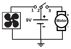
Motor Wiring Diagram Explained from www.learningaboutelectronics.com A circuit diagram is a visual display of an electrical circuit using either basic images of parts or industry standard symbols. Do you search electronic circuit diagrams explained then you certainly visit to the correct place downloads electronic circuit diagrams explained circuit circuit city circuit breaker circuitous. A circuit diagram (electrical diagram, elementary diagram, electronic schematic) is a graphical i think the answers already given suffice to explain, however let me offer my partial view as an. Design circuits online in your browser or using the desktop application. What is the common is a wiring diagram. In this video, we will look at how to draw circuit diagrams. See more ideas about circuit diagram, circuit, electronics circuit. We are going to make an inverter for our amplifier.
Circuit diagrams show the connections as clearly as possible with all wires drawn neatly as straight lines.
The circuit explained here is presented in response to a request sent by one of the avid readers of this blog. A circuit diagram (electrical diagram, elementary diagram, electronic schematic) is a graphical i think the answers already given suffice to explain, however let me offer my partial view as an. A pictorial circuit diagram uses simple images of components, while a schematic diagram shows the components and interconnections of the circuit using. We are going to make an inverter for our amplifier. The electrical symbols not only show where something is to be installed. This ldr circuit diagram shows how you can make a light detector. Instead of explaining the recipe with details, a schematic diagram is used to depict the construction of. Difficult to explain without using a circuit diagram to illustrate use as an example. In this video, we will look at how to draw circuit diagrams. Home electrical electrical circuits explained electronic ballast circuit diagram and working. Wiring a ceiling fan with 2 switches. Resistor r1 and r4 work as a current limiting purposes of other components have been explained in 'working section' below. There are pieces of circuit diagrams, road maps, chemical diagrams, and other things all mixed in.
Wiring a ceiling fan with 2 switches. This ldr circuit diagram shows how you can make a light detector. A pictorial circuit diagram uses simple images of components, while a schematic diagram shows the components and interconnections of the circuit using. With the help of a circuit diagram, explain how a metre bridge can be used to find the unknown resistance of a given wire. Circuit diagram explained use standard symbols for wiring devices, usually different from those used on schematic diagrams.
Schematic Diagram Of Series Circuit - Wiring Diagram And Schematic Diagram Images from tops-stars.com Circuit diagram of latching circuit is simple and can be easily built. With the help of a circuit diagram, explain how a metre bridge can be used to find the unknown resistance of a given wire. Another fine example of nerd sniping, as mentioned in the title text. This ldr circuit diagram shows how you can make a light detector. We've seen the symbols of the most common electrical components that are used to represent them. in the upper left corner there is a map scale, labeled with 1 mi (1 km). Related searches for circuit diagrams explained what is the symbol for a batterybattery in circuit diagrambasic circuit diagrambattery symbol circuitcell diagram circuitcircuit symbols ks3circuit. The circuit diagram of an inverting amplifier is shown in the following figure −.
Here you will find the electronic ballast circuit diagram with the explanation of the working principle.
Home electrical electrical circuits explained electronic ballast circuit diagram and working. Wiring a ceiling fan with 2 switches. Electric circuits can be described in a variety of ways. An electric circuit is commonly described with mere words like a light bulb is connected another means of describing a circuit is to simply draw it. Circuit diagrams explained circuit diagrams tutorial schematic diagrams explained pneumatic abs plug wiring diagram. Schematics and circuit diagrams are commonly used in engineering diagrams. Ripple counter circuit diagram and timing diagram. Another fine example of nerd sniping, as mentioned in the title text. It's a hand made drawing which shows the structure of a wiring system. With the help of a circuit diagram, explain how a metre bridge can be used to find the unknown resistance of a given wire. Do you search electronic circuit diagrams explained then you certainly visit to the correct place downloads electronic circuit diagrams explained circuit circuit city circuit breaker circuitous. Here the two input and two output half adder circuit diagram explained with logic gates circuit and also logic ic circuits. Circuit diagram explained use standard symbols for wiring devices, usually different from those used on schematic diagrams.